Customer Requirements
After the connection is made to the ISP, the business or customer must decide which services they need from the ISP.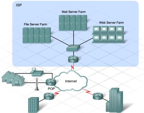
ISPs serve several markets. Individuals in homes make up the consumer market. Large, multinational companies make up the enterprise market. In between are smaller markets, such as small- to medium-sized businesses, or larger nonprofit organizations. Each of these customers have different service requirements.
Escalating customer expectations and increasingly competitive markets are forcing ISPs to offer new services. These services enable the ISPs to increase revenue and to differentiate themselves from their competitors.
Email, web hosting, media streaming, IP telephony, and file transfer are important services that ISPs can provide to all customers. These services are critical for the ISP consumer market and for the small- to medium-sized business that does not have the expertise to maintain their own services.
Many organizations, both large and small, find it expensive to keep up with new technologies, or they simply prefer to devote resources to other parts of the business. ISPs offer managed services that enable these organizations to have access to the leading network technologies and applications without having to make large investments in equipment and support.
When a company subscribes to a managed service, the service provider manages the network equipment and applications according to the terms of a service level agreement (SLA). Some managed services are also hosted, meaning that the service provider hosts the applications in its facility instead of at the customer site.
The following are three scenarios that describe different ISP customer relationships:
– Scenario 1 – The customer owns and manages all their own network equipment and services. These customers only need reliable Internet connectivity from the ISP.
– Scenario 2 – The ISP provides Internet connectivity. The ISP also owns and manages the network connecting equipment installed at the customer site. ISP responsibilities include setting up, maintaining, and administering the equipment for the customer. The customer is responsible for monitoring the status of the network and the applications, and receives regular reports on the performance of the network.
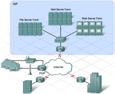
– Scenario 3 – The customer owns the network equipment, but the applications that the business relies on are hosted by the ISP. The actual servers that run the applications are located at the ISP facility. These servers may be owned by the customer or the ISP, although the ISP maintains both the servers and the applications. Servers are normally kept in server farms in the ISP network operations center (NOC), and are connected to the ISP network with a high-speed switch.
Reliability & Availability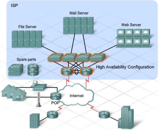
Creating new services can be challenging. Not only must ISPs understand what their customers want, but they must have the ability and the resources to provide those services. As business and Internet applications become more complex, an increasing number of ISP customers rely on the services provided or managed by the ISP.
ISPs provide services to customers for a fee and guarantee a level of service in the SLA. To meet customer expectations, the service offerings have to be reliable and available.
Reliability
Reliability can be measured in two ways: mean time between failure (MTBF) and mean time to repair MTTR. Equipment manufacturers specify MTBF based on tests they perform as part of manufacturing. The measure of equipment robustness is fault tolerance. The longer the MTBF, the greater the fault tolerance. MTTR is established by warranty or service agreements.
When there is an equipment failure, and the network or service becomes unavailable, it impacts the ability of the ISP to meet the terms of the SLA. To prevent this, an ISP may purchase expensive service agreements for critical hardware to ensure rapid manufacturer or vendor response. An ISP may also choose to purchase redundant hardware and keep spare parts on site.
Availability
Availability is normally measured in the percentage of time that a resource is accessible. A perfect availability percentage is 100%, meaning that the system is never down or unreachable. Traditionally, telephone services are expected to be available 99.999% of the time. This is called the five-9s standard of availability. With this standard, only a very small percentage (0.001%) of downtime is acceptable. As ISPs offer more critical business services, such as IP telephony or high-volume retail sale transactions, ISPs must meet the higher expectations of their customers. ISPs ensure accessibility by doubling up on network devices and servers using technologies designed for high availability. In redundant configurations, if one device fails, the other one can take over the functions automatically.
Review of TCP/IP Protocols
Today, ISP customers are using mobile phones as televisions, PCs as telephones, and televisions as interactive gaming stations with many different entertainment options. As network services become more advanced, ISPs must accommodate these customer preferences. The development of converged IP networks enables all of these services to be delivered over a common network.
To provide support for the multiple end-user applications that rely on TCP/IP for delivery, it is important for the ISP support personnel to be familiar with the operation of the TCP/IP protocols.
ISP servers need to be able to support multiple applications for many different customers. For this support, they must use functions provided by the two TCP/IP transport protocols, TCP and UDP. Common hosted applications, like web serving and email accounts, also depend on underlying TCP/IP protocols to ensure their reliable delivery. In addition, all IP services rely on domain name servers, hosted by the ISPs, to provide the link between the IP addressing structure and the URLs that customers use to access them.
Clients and servers use specific protocols and standards when exchanging information. The TCP/IP protocols can be represented using a four-layer model. Many of the services provided to ISP customers depend on protocols that reside at the Application and Transport layers of the TCP/IP model.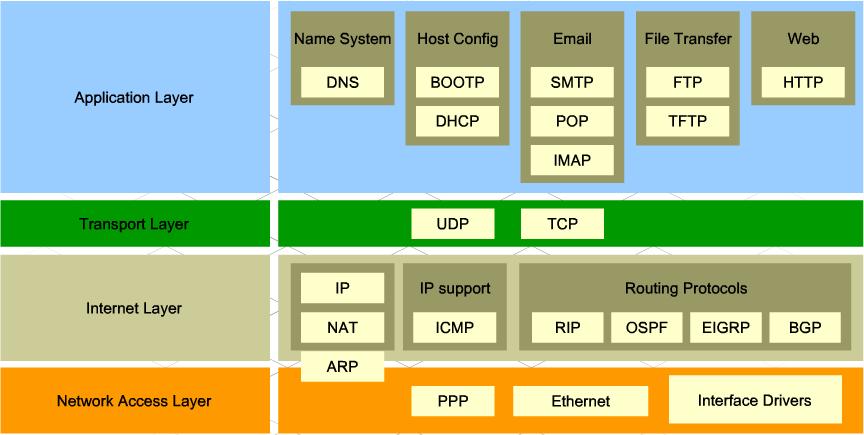
Application Layer Protocols
Application Layer protocols specify the format and control the information necessary for many of the common Internet communication functions. Among these protocols are:
– Domain Name System (DNS) – Resolves Internet names to IP addresses.
– HyperText Transfer Protocol (HTTP) -Transfers files that make up the web pages of the World Wide Web.
– Simple Mail Transfer Protocol (SMTP) – Transfers mail messages and attachments.
– Telnet – Terminal emulation protocol that provides remote access to servers and networking devices.
– File Transfer Protocol (FTP) – Transfers files between systems interactively.
Transport Layer Protocols
Different types of data can have unique requirements. For some applications, communication segments must arrive in a specific sequence to be processed successfully. In other instances, all the data must be received for any of it to be of use. Sometimes, an application can tolerate the loss of a small amount of data during transmission over the network.
In today’s converged networks, applications with very different transport needs may be communicating on the same network. Different Transport Layer protocols have different rules to enable devices to handle these diverse data requirements.
Additionally, the lower layers are not aware that there are multiple applications sending data on the network. Their responsibility is to get the data to the device. It is the job of the Transport Layer to deliver the data to the appropriate application.
 The two primary Transport Layer protocols are TCP and UDP.
The TCP/IP model and the OSI model have similarities and differences.
Similarities
– Use of layers to visualize the interaction of protocols and services
– Comparable Transport and Network layers
– Used in the networking field when referring to protocol interaction
Differences
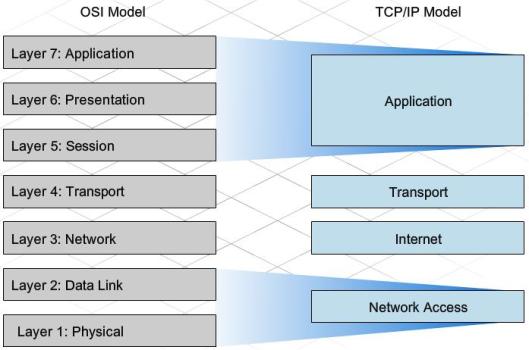
– OSI model breaks the function of the TCP/IP Application Layer into distinct layers. The upper three layers of the OSI model specify the same functionality as the Application Layer of the TCP/IP model.
– The TCP/IP suite does not specify protocols for the physical network interconnection. The two lower layers of the OSI model are concerned with access to the physical network and the delivery of bits between hosts on a local network.
The TCP/IP model is based on actual developed protocols and standards, whereas the OSI model is a theoretical guide for how protocols interact.
Transport Layer Protocols
Different applications have different transport needs. There are two protocols at the Transport Layer: TCP and UDP.
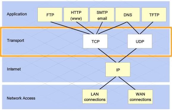 TCP
TCP
TCP is a reliable, guaranteed-delivery protocol. TCP specifies the methods hosts use to acknowledge the receipt of packets, and requires the source host to resend packets that are not acknowledged. TCP also governs the exchange of messages between the source and destination hosts to create a communication session. TCP is often compared to a pipeline, or a persistent connection, between hosts. Because of this, TCP is referred to as a connection-oriented protocol.
TCP requires overhead, which includes extra bandwidth and increased processing, to keep track of the individual conversations between the source and destination hosts and to process acknowledgements and retransmissions. In some cases, the delays caused by this overhead cannot be tolerated by the application. These applications are better suited for UDP.
UDP
UDP is a very simple, connectionless protocol. It provides low overhead data delivery. UDP is considered a “best effort” Transport Layer protocol because it does not provide error checking, guaranteed data delivery, or flow control. Because UDP is a “best effort” protocol, UDP datagrams may arrive at the destination out of order, or may even be lost all together. Applications that use UDP can tolerate small amounts of missing data. An example of a UDP application is Internet radio. If a piece of data is not delivered, there may only be a minor effect on the quality of the broadcast.
Applications, such as databases, web pages, and email, need to have all data arrive at the destination in its original condition, for the data to be useful. Any missing data can cause the messages to be corrupt or unreadable. These applications are designed to use a Transport Layer protocol that implements reliability. The additional network overhead required to provide this reliability is considered a reasonable cost for successful communication.
The Transport Layer protocol is determined by the type of application data being sent. For example, an email message requires acknowledged delivery and therefore would use TCP. An email client, using SMTP, sends an email message as a stream of bytes to the Transport Layer. At the Transport Layer, the TCP functionality divides the stream into segments.
Within each segment, TCP identifies each byte, or octet, with a sequence number. These segments are passed to the Internet Layer, which places each segment in a packet for transmission. This process is known as encapsulation. At the destination, the process is reversed, and the packets are de-encapsulated. The enclosed segments are sent through the TCP process, which converts the segments back to a stream of bytes to be passed to the email server application.
Before a TCP session can be used, the source and destination hosts exchange messages to set up the connection over which data segments can be sent. The two hosts use a three step process to set up the connection.
In the first step, the source host sends a type of message, called a Synchronization Message, or SYN, to begin the TCP session establishment process. The message serves two purposes:
– It indicates the intention of the source host to establish a connection with the destination host over which to send the data.
– It synchronizes the TCP sequence numbers between the two hosts, so that each host can keep track of the segments sent and received during the conversation.
For the second step, the destination host replies to the SYN message with a synchronization acknowledgement, or SYN-ACK, message.
In the last step, the sending host receives the SYN-ACK and it sends an ACK message back to complete the connection setup. Data segments can now be reliably sent.
This SYN, SYN-ACK, ACK activity between the TCP processes on the two hosts is called a three-way handshake.
When a host sends message segments to a destination host using TCP, the TCP process on the source host starts a timer. The timer allows sufficient time for the message to reach the destination host and for an acknowledgement to be returned. If the source host does not receive an acknowledgement from the destination within the allotted time, the timer expires, and the source assumes the message is lost. The portion of the message that was not acknowledged is then re-sent.
In addition to acknowledgement and retransmission, TCP also specifies how messages are reassembled at the destination host. Each TCP segment contains a sequence number. At the destination host, the TCP process stores received segments in a buffer. By evaluating the segment sequence numbers, the TCP process can confirm that there are no gaps in the received data. When data is received out of order, TCP can also reorder the segments as necessary.
Differences Between TCP & UDP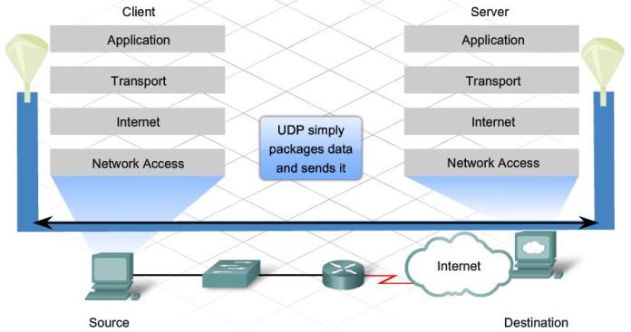
UDP is a very simple protocol. Because it is not connection-oriented and does not provide the sophisticated retransmission, sequencing, and flow control mechanisms of TCP, UDP has a much lower overhead.
UDP is often referred to as an unreliable delivery protocol, because there is no guarantee that a message has been received by the destination host. This does not mean that applications that use UDP are unreliable. It simply means that these functions are not provided by the Transport Layer protocol and must be implemented elsewhere if required.
Although the total amount of UDP traffic found on a typical network is often relatively low, Application Layer protocols that do use UDP include:
– Domain Name System (DNS)
– Simple Network Management Protocol (SNMP)
– Dynamic Host Configuration Protocol (DHCP)
– RIP routing protocol
– Trivial File Transfer Protocol (TFTP)
– Online games
The main differences between TCP and UDP are the specific functions that each protocol implements and the amount of overhead incurred. Viewing the headers of both protocols is an easy way to see the differences between them.
Each TCP segment has 20 bytes of overhead in the header that encapsulates the Application Layer data. This overhead is incurred because of the error-checking mechanisms supported by TCP.
The pieces of communication in UDP are called datagrams. These datagrams are sent as “best effort” and, therefore, only require 8 bytes of overhead.
Supporting Multiple Services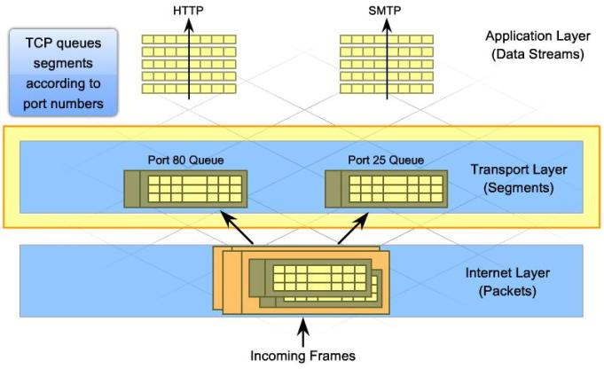
The task of managing multiple simultaneous communication processes is done at the Transport Layer. The TCP and UDP services keep track of the various applications that are communicating over the network. To differentiate the segments and datagrams for each application, both TCP and UDP have header fields that can uniquely identify these applications for data communications purposes.
A source port and destination port are located in the header of each segment or datagram. Port numbers are assigned in various ways, depending on whether the message is a request or a response. When a client application sends a request to a server application, the destination port contained in the header is the port number that is assigned to the application running on the server. For example, when a web browser application makes a request to a web server, the browser uses TCP and port number 80. This is because TCP port 80 is the default port assigned to web-serving applications. Many common applications have default port assignments. Email servers that are using SMTP are usually assigned to TCP port 25.
As segments are received for a specific port, TCP or UDP places the incoming segments in the appropriate queue. For instance, if the application request is for HTTP, the TCP process running on a web server places incoming segments in the web server queue. These segments are then passed up to the HTTP application as quickly as HTTP can accept them.
Segments with port 25 specified are placed in a separate queue that is directed toward email services. In this manner, Transport Layer protocols enable servers at the ISP to host many different applications and services simultaneously.
In any Internet transaction, there is a source host and a destination host, normally a client and a server. The TCP processes on the sending and receiving hosts are slightly different. Clients are active and request connections, while servers are passive, and listen for and accept connections.
Server processes are usually statically assigned well-known port numbers from 0 to 1023. Well-known port numbers enable a client application to assign the correct destination port when generating a request for services.
Clients also require port numbers to identify the requesting client application. Source ports are dynamically assigned from the port range 1024 to 65535. This port assignment acts like a return address for the requesting application. The Transport Layer protocols keep track of the source port and the application that initiated the request, so that when a response is returned, it can be forwarded to the correct application.
The combination of the Transport Layer port number and the Network Layer IP address of the host uniquely identifies a particular application process running on an individual host device. This combination is called a socket. A socket pair, consisting of the source and destination IP addresses and port numbers, is also unique and identifies the specific conversation between the two hosts.
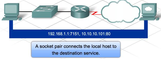 A client socket might look like this, with 7151 representing the source port number:
192.168.1.1:7151
The socket on a web server might be:
10.10.10.101:80
Together, these two sockets combine to form a socket pair:
192.168.1.1:7151, 10.10.10.101:80
With the creation of sockets, communication endpoints are known so that data can move from an application on one host to an application on another. Sockets enable multiple processes running on a client to distinguish themselves from each other, and multiple connections to a server process to be distinguished from each other.
TCP/IP Host Name
Communication between source and destination hosts over the Internet requires a valid IP address for each host. However, numeric IP addresses, especially the hundreds of thousands of addresses assigned to servers available over the Internet, are difficult for humans to remember. Human-readable domain names, like cisco.com, are easier for people to use. Network naming systems are designed to translate human-readable names into machine-readable IP addresses that can be used to communicate over the network.
Humans use network naming systems every day when surfing the web or sending email messages, and may not even realize it. Naming systems work as a hidden but integral part of network communication. For example, to browse to the Cisco Systems website, open a browser and enter http://www.cisco.com in the address field. The http://www.cisco.com is a network name that is associated with a specific IP address. Typing the server IP address into the browser brings up the same web page.
Network naming systems are a human convenience to help users reach the resource they need without having to remember the complex IP address.
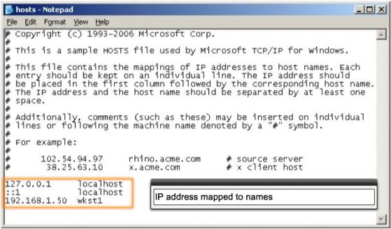 In the early days of the Internet, host names and IP addresses were managed through the use of a single HOSTS file located on a centrally administered server.
The central HOSTS file contained the mapping of the host name and IP address for every device connected to the early Internet. Each site could download the HOSTS file and use it to resolve host names on the network. When a host name was entered, the sending host would check the downloaded HOSTS file to obtain the IP address of the destination device.
At first, the HOSTS file was acceptable for the limited number of computer systems participating in the Internet. As the network grew, so did the number of hosts needing name-to-IP translations. It became impossible to keep the HOSTS file up to date. As a result, a new method to resolve host names to IP addresses was developed. DNS was created for domain name to address resolution. DNS uses a distributed set of servers to resolve the names associated with the numbered addresses. The single, centrally administered HOSTS file is no longer needed.
However, virtually all computer systems still maintain a local HOSTS file. A local HOSTS file is created when TCP/IP is loaded on a host device. As part of the name resolution process on a computer system, the HOSTS file is scanned even before the more robust DNS service is queried. A local HOSTS file can be used for troubleshooting or to override records found in a DNS server.
DNS Hierarchy
DNS solves the shortcomings of the HOSTS file. The structure of DNS is hierarchical, with a distributed database of host name to IP mappings spread across many DNS servers all over the world. This is unlike a HOSTS file, which requires all mappings to be maintained on one server.
DNS uses domain names to form the hierarchy. The naming structure is broken down into small, manageable zones. Each DNS server maintains a specific database file and is only responsible for managing name-to-IP mappings for that small portion of the entire DNS structure. When a DNS server receives a request for a name translation that is not within its DNS zone, the DNS server forwards the request to another DNS server within the proper zone for translation.
DNS is scalable because host name resolution is spread across multiple servers.
 DNS is made up of three components.
Resource Records and Domain Namespace
A resource record is a data record in the database file of a DNS zone. It is used to identify a type of host, a host IP address, or a parameter of the DNS database.
The domain namespace refers to the hierarchical naming structure for organizing resource records. The domain namespace is made up of various domains, or groups, and the resource records within each group.
Domain Name System Servers
Domain name system servers maintain the databases that store resource records and information about the domain namespace structure. DNS servers attempt to resolve client queries using the domain namespace and resource records it maintains in its zone database files. If the name server does not have the requested information in its DNS zone database, it uses additional predefined name servers to help resolve the name-to-IP query.
Resolvers
Resolvers are applications or operating system functions that run on DNS clients and DNS servers. When a domain name is used, the resolver queries the DNS server to translate that name to an IP address. A resolver is loaded on a DNS client, and is used to create the DNS name query that is sent to a DNS server. Resolvers are also loaded on DNS servers. If the DNS server does not have the name-to-IP mapping requested, it uses the resolver to forward the request to another DNS server.
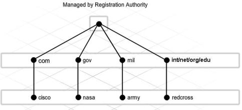 DNS uses a hierarchical system to provide name resolution. The hierarchy looks like an inverted tree, with the root at the top and branches below.
At the top of the hierarchy, the root servers maintain records about how to reach the top-level domain servers, which in turn have records that point to the second-level domain servers.
The different top-level domains represent either the type of organization or the country of origin. Examples of top-level domains are:
.au – Australia
.co – Colombia
.com – a business or industry
.jp – Japan
.org – a nonprofit organization
 Under top-level domains are second-level domain names, and below them are other lower level domains.
The root DNS server may not know exactly where the host H1.cisco.com is located, but it does have a record for the .com top-level domain. Likewise, the servers within the .com domain may not have a record for H1.cisco.com either, but they do have a record for the cisco.com domain. The DNS servers within the cisco.com domain do have the record for H1.cisco.com and can resolve the address.
DNS relies on this hierarchy of decentralized servers to store and maintain these resource records. The resource records contain domain names that the server can resolve, and alternate servers that can also process requests.
The name H1.cisco.com is referred to as a fully qualified domain name (FQDN) or DNS name, because it defines the exact location of the computer within the hierarchical DNS namespace.
DNS Name Resolution
When a host needs to resolve a DNS name, it uses the resolver to contact a DNS server within its domain. The resolver knows the IP address of the DNS server to contact because it is preconfigured as part of the host IP configuration.
When the DNS server receives the request from the client resolver, it first checks the local DNS records it has cached in its memory. If it is unable to resolve the IP address locally, the server uses its resolver to forward the request to another preconfigured DNS server. This process continues until the IP address is resolved. The name resolution information is sent back to the original DNS server, which uses the information to respond to the initial query.
During the process of resolving a DNS name, each DNS server caches, or stores, the information it receives as replies to the queries. The cached information enables the DNS server to reply more quickly to subsequent resolver requests, because the server first checks the cache records before querying other DNS servers.
DNS servers only cache information for a limited amount of time. DNS servers should not cache information for too long because host name records do periodically change. If a DNS server had old information cached, it may give out the wrong IP address for a computer.
In the early implementations of DNS, resource records for hosts were all added and updated manually. However, as networks grew and the number of host records needing to be managed increased, it became very inefficient to maintain the resource records manually. Furthermore, when DHCP is used, the resource records within the DNS zone have to be updated even more frequently. To make updating the DNS zone information easier, the DNS protocol was changed to allow computer systems to update their own record in the DNS zone through dynamic updates.
Dynamic updates enable DNS client computers to register and dynamically update their resource records with a DNS server whenever changes occur. To use dynamic update, the DNS server and the DNS clients, or DHCP server, must support the dynamic update feature. Dynamic updates on the DNS server are not enabled by default, and must be explicitly enabled. Most current operating systems support the use of dynamic updates.
DNS servers maintain the zone database for a given portion of the overall DNS hierarchy. Resource records are stored within that DNS zone.
DNS zones can be either a forward lookup or reverse lookup zone. They can also be either a primary or a secondary forward or reverse lookup zone. Each zone type has a specific role within the overall DNS infrastructure.
Forward Lookup Zones
A forward lookup zone is a standard DNS zone that resolves fully qualified domain names to IP addresses. This is the zone type that is most commonly found when surfing the Internet. When typing a website address, such as http://www.cisco.com, a recursive query is sent to the local DNS server to resolve that name to an IP address to connect to the remote web server.
Reverse Lookup Zones
A reverse lookup zone is a special zone type that resolves an IP address to a fully qualified domain name. Some applications use reverse lookups to identify computer systems that are actively communicating with them. There is an entire reverse lookup DNS hierarchy on the Internet that enables any publicly registered IP address to be resolved. Many private networks choose to implement their own local reverse lookup zones to help identify computer systems within their network. Reverse lookups on IP addresses can be found using the ping -a [ip_address] command.
Primary Zones
A primary DNS zone is a zone that can be modified. When a new resource record needs to be added or an existing record needs to be updated or deleted, the change is made on a primary DNS zone. When you have a primary zone on a DNS server, that server is said to be authoritative for that DNS zone, since it will have the answer for DNS queries for records within that zone. There can only be one primary DNS zone for any given DNS domain; however, you can have a primary forward and primary reverse lookup zone.
Secondary Zones
A secondary zone is a read-only backup zone maintained on a separate DNS server than the primary zone. The secondary zone is a copy of the primary zone and receives updates to the zone information from the primary server. Since the secondary zone is a read-only copy of the zone, all updates to the records need to be done on the corresponding primary zone. You can also have secondary zones for both forward and reverse lookup zones. Depending on the availability requirements for a DNS zone, you may have many secondary DNS zones spread across many DNS servers.
 Implimenting DNS Solutions
There is more than one way to implement DNS solutions.
ISP DNS Servers
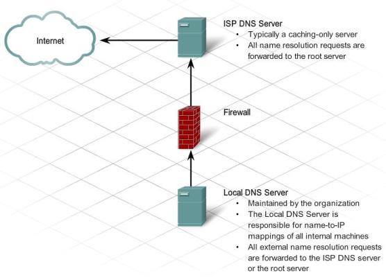
ISPs typically maintain caching-only DNS servers. These servers are configured to forward all name resolution requests to the root servers on the Internet. Results are cached and used to reply to any future requests. Because ISPs typically have many customers, the number of cached DNS lookups is high. The large cache reduces network bandwidth by reducing the frequency that DNS queries that are forwarded to the root servers. Caching-only servers do not maintain any authoritative zone information, meaning that they do not store any name-to-IP mappings directly within their database.
Local DNS Servers
A business may run its own DNS server. The client computers on that network are configured to point to the local DNS server rather than the ISP DNS server. The local DNS server may maintain some authoritative entries for that zone, so it has name-to-IP mappings of any host within the zone. If the DNS server receives a request that it cannot resolve, it is forwarded. The cache required on a local server is relatively small compared to the ISP DNS server because of the smaller number of requests.
It is possible to configure local DNS servers to forward requests directly to the root DNS server. However, some administrators configure local DNS servers to forward all DNS requests to an upstream DNS server, such as the DNS server of the ISP. In this way, the local DNS server benefits from the large number of cached DNS entries of the ISP, rather than having to go through the entire lookup process starting from the root server.
Losing access to DNS servers affects the visibility of public resources. If users type in a domain name that cannot be resolved, they cannot access the resource. For this reason, when an organization registers a domain name on the Internet, a minimum of two DNS servers must be provided with the registration. These servers are the ones that hold the DNS zone database. Redundant DNS servers ensure that if one fails, the other one is available for name resolution. This practice provides fault tolerance. If hardware resources permit, having more than two DNS servers within a zone provides additional protection and organization.
It is also a good idea to make sure that multiple DNS servers that host the zone information are located on different physical networks. For example, the primary DNS zone information can be stored on a DNS server on the local business premises. Usually the ISP hosts an additional secondary DNS server to ensure fault tolerance.
DNS is a critical network service. Therefore, DNS servers must be protected using firewalls and other security measures. If DNS fails, other web services are not accessible.
 Services
In addition to providing private and business customers with connectivity and DNS services, ISPs provide many business-oriented services to customers. These services are enabled by software installed on servers. Among the different services provided by ISPs are:
– email hosting
– website hosting
– e-commerce sites
– file storage and transfer
– message boards and blogs
– streaming video and audio services
TCP/IP Application Layer protocols enable many of these ISP services and applications. The most common TCP/IP Application Layer protocols are HTTP, FTP, SMTP, POP3, and IMAP4.
Some customers have greater concern about security, so these Application Layer protocols also include secure versions such as FTPS and HTTPS.
HTTP & HTTPS
HTTP, one of the protocols in the TCP/IP suite, was originally developed to enable the retrieval of HTML-formatted web pages. It is now used for distributed, collaborative information sharing. HTTP has evolved through multiple versions. Most ISPs use HTTP version 1.1 to provide web-hosting services. Unlike earlier versions, version 1.1 enables a single web server to host multiple websites. It also permits persistent connections, so that multiple request and response messages can use the same connection, reducing the time it takes to initiate new TCP sessions.

HTTP specifies a request/response protocol. When a client, typically a web browser, sends a request message to a server, HTTP defines the message types that the client uses to request the web page. It also defines the message types that the server uses to respond.
Although it is remarkably flexible, HTTP is not a secure protocol. The request messages send information to the server in plain text that can be intercepted and read. Similarly, the server responses, typically HTML pages, are also sent unencrypted.
For secure communication across the Internet, Secure HTTP (HTTPS) is used for accessing or posting web server information. HTTPS can use authentication and encryption to secure data as it travels between the client and server. HTTPS specifies additional rules for passing data between the Application Layer and the Transport Layer.
When contacting an HTTP server to download a web page, a uniform resource locator (URL) is used to locate the server and a specific resource. The URL identifies:
– Protocol being used
– Domain name of the server being accessed
 – Location of the resource on the server, such as http://example.com/example1/index.htm
Many web server applications allow short URLs. Short URLs are popular because they are easier to write down, remember, or share. With a short URL, a default resource page is assumed when a specific URL is typed. When a user types in a shortened URL, like http://example.com, the default page that is sent to the user is actually the http://example.com/example1/index.htm web page.
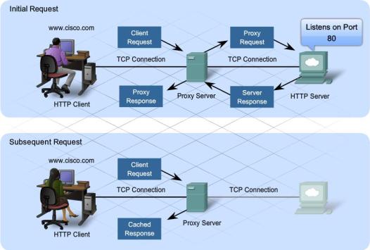
HTTP supports proxy services. A proxy server allows clients to make indirect network connections to other network services. A proxy is a device in the communications stream that acts as a server to the client and as a client to a server.
The client connects to the proxy server and requests from the proxy a resource on a different server. The proxy connects to the specified server and retrieves the requested resource. It then forwards the resource back to the client.
The proxy server can cache the resulting page or resource for a configurable amount of time. Caching enables future clients to access the web page quickly, without having to access the actual server where the page is stored. Proxies are used for three reasons:
– Speed – Caching allows resources requested by one user to be available to subsequent users, without having to access the actual server where the page is stored.
– Security – Proxy servers can be used to intercept computer viruses and other malicious content and prevent them from being forwarded onto clients.
– Filtering – Proxy servers can view incoming HTTP messages and filter unsuitable and offensive web content.
HTTP sends clear text messages back and forth between a client and a server. These text messages can be easily intercepted and read by unauthorized users. To safeguard data, especially confidential information, some ISPs provide secure web services by using HTTPS. HTTPS is HTTP over secure socket layer (SSL). HTTPS uses the same client request-server response process as HTTP, but the data stream is encrypted with SSL before being transported across the network.
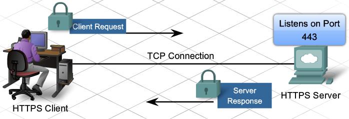
When the HTTP data stream arrives at the server, the TCP layer passes it up to SSL in the Application Layer of the server, where it is decrypted.
The maximum number of simultaneous connections that a server can support for HTTPS is less than that for HTTP. HTTPS creates additional load and processing time on the server due to the encryption and decryption of traffic. To keep server performance up, HTTPS should only be used when necessary, such as when exchanging confidential information.
FTP
FTP is a connection-oriented protocol that uses TCP to communicate between a client FTP process and an FTP process on a server. FTP implementations include the functions of a protocol interpreter (PI) and a data transfer process (DTP). PI and DTP define two separate processes that work together to transfer files. As a result, FTP requires two connections to exist between the client and server, one to send control information and commands, and a second one for the actual file data transfer.
Protocol Interpreter (PI)
The PI function is the main control connection between the FTP client and the FTP server. It establishes the TCP connection and passes control information to the server. Control information includes commands to navigate through a file hierarchy and renaming or moving files. The control connection, or control stream, stays open until closed by the user. When a user wants to connect to an FTP server there are five basic steps:
– Step 1. The user PI sends a connection request to the server PI on well-known port 21.
– Step 2. The server PI replies and the connection is established.
– Step 3. With the TCP control connection open, the server PI process begins the login sequence.
– Step 4. The user enters credentials through the user interface and completes authentication.
– Step 5. The data transfer process begins.
Data Transfer Process
DTP is a separate data transfer function. This function is enabled only when the user wants to actually transfer files to or from the FTP server. Unlike the PI connection, which remains open, the DTP connection closes automatically when the file transfer is complete.
The two types of data transfer connections supported by FTP are active data connections and passive data connections.
Active Data Connections
In an active data connection, a client initiates a request to the server and opens a port for the expected data. The server then connects to the client on that port and the file transfer begins.
Passive Data Connections
In a passive data connection, the FTP server opens a random source port (greater than 1023). The server forwards its IP address and the random port number to the FTP client over the control stream. The server then waits for a connection from the FTP client to begin the data file transfer.
ISPs typically support passive data connections to their FTP servers. Firewalls often do not permit active FTP connections to hosts located on the inside network.
 SMTP, POP3, & IMAP4
One of the primary services offered by an ISP is email hosting. Email is a store-and-forward method of sending, storing, and retrieving electronic messages across a network. Email messages are stored in databases on mail servers. ISPs often maintain mail servers that support many different customer accounts.
Email clients communicate with mail servers to send and receive email. Mail servers communicate with other mail servers to transport messages from one domain to another. An email client does not communicate directly with another email client when sending email. Instead, both clients rely on the mail server to transport messages. This is true even when both users are in the same domain.
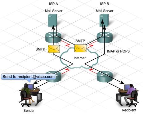
Email clients send messages to the email server configured in the application settings. When the server receives the message, it checks to see if the recipient domain is located on its local database. If it is not, it sends a DNS request to determine the mail server for the destination domain. When the IP address of the destination mail server is known, the email is sent to the appropriate server.
Email supports three separate protocols for operation: SMTP, POP3, and IMAP4. The Application Layer process that sends mail, either from a client to a server or between servers, implements SMTP. A client retrieves email using one of two Application Layer protocols: POP3 or IMAP4.
SMTP transfers mail reliably and efficiently. For SMTP applications to work properly, the mail message must be formatted properly and SMTP processes must be running on both the client and server.
SMTP message formats require a message header and a message body. While the message body can contain any amount of text, the message header must have a properly formatted recipient email address and a sender address. Any other header information is optional.
 When a client sends email, the client SMTP process connects with a server SMTP process on well-known port 25. After the connection is made, the client attempts to send mail to the server across the connection. When the server receives the message, it either places the message in a local account or forwards the message using the same SMTP connection process to another mail server.
The destination email server may not be online or may be busy when email messages are sent. Therefore, SMTP spools messages to be sent at a later time. Periodically, the server checks the queue for messages and attempts to send them again. If the message is still not delivered after a predetermined expiration time, it is returned to the sender as undeliverable.
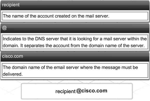
One of the required fields in an email message header is the recipient email address. The structure of an email address includes the email account name or an alias, in addition to the domain name of the mail server. An example of an email address:
recipient@cisco.com.
The @ symbol separates the account and the domain name of the server. When a DNS server receives a query for a name with an @ symbol, that indicates to the DNS server that it is looking up an IP address for a mail server.
When a message is sent to recipient@cisco.com, the domain name is sent to the DNS server to obtain the IP address of the domain mail server. Mail servers are identified in DNS by an MX record indicator. MX is a type of resource record stored on the DNS server. When the destination mail server receives the message, it stores the message in the appropriate mailbox. The mailbox location is determined based on the account specified in the first part of the email address, in this case, the recipient account. The message remains in the mailbox until the recipient connects to the server to retrieve the email.
If the mail server receives an email message that references an account that does not exist, the email is returned to the sender as undeliverable.
Post Office Protocol – Version 3 (POP3) enables a workstation to retrieve mail from a mail server. With POP3, mail is downloaded from the server to the client and then deleted on the server.
The server starts the POP3 service by passively listening on TCP port 110 for client connection requests. When a client wants to make use of the service, it sends a request to establish a TCP connection with the server. When the connection is established, the POP3 server sends a greeting. The client and POP3 server then exchange commands and responses until the connection is closed or aborted.
Because email messages are downloaded to the client and removed from the server, there is not a centralized location where email messages are kept. Because POP3 does not store messages, it is undesirable for a small business that needs a centralized backup solution.
POP3 is desirable for an ISP, because it alleviates their responsibility for managing large amounts of storage for their email servers.
Internet Message Access Protocol (IMAP4) is another protocol that describes a method to retrieve email messages. However, unlike POP3, when the user connects to an IMAP-capable server, copies of the messages are downloaded to the client application. The original messages are kept on the server until manually deleted. Users view copies of the messages in their email client software.
Users can create a file hierarchy on the server to organize and store mail. That file structure is duplicated on the email client as well. When a user decides to delete a message, the server synchronizes that action and deletes the message from the server.
For small- to medium-sized businesses, there are many advantages to using IMAP. IMAP can provide long-term storage of email messages on mail servers and allows for centralized backup. It also enables employees to access email messages from multiple locations, using different devices or client software. The mailbox folder structure that a user expects to see is available for viewing regardless of how the user accesses the mailbox.
For an ISP, IMAP may not be the protocol of choice. It can be expensive to purchase and maintain the disk space to support the large number of stored emails. Additionally, if customers expect their mailboxes to be backed up routinely, that can further increase the costs to the ISP.
Leave a comment